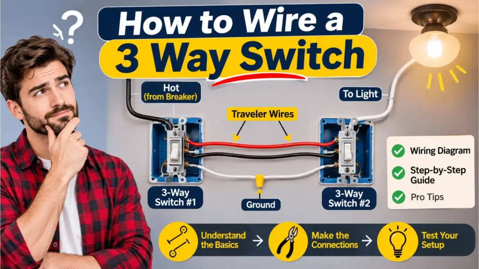
How to Wire a 3-Way Switch: Step-by-Step With Diagrams
Here’s the short answer on how to wire a 3 way switch: turn off the breaker, then connect the incoming hot (black) wire to the dark “common” screw on the first switch, run two traveler wires (usually red and black in a 3-conductor cable) between the brass screws on both switches, connect the second switch’s common screw to the wire going to the light, splice the white neutrals straight through to the light, and connect all grounds to the green screws.
A 3-way switch setup uses two 3-way switches to control one light (or a group of lights) from two places, such as the top and bottom of a staircase or both ends of a hallway. This guide covers how 3-way switches work, the wires and terminals, the most common wiring layouts, how to replace an existing switch, smart switch options, and how to fix common problems.
Safety note: Electrical work can cause shock, fire, and serious injury. Many areas require a permit or a licensed electrician for new wiring. If you’re unsure at any step, stop and call a licensed electrician.
What Is a 3-Way Switch?
Despite the name, a 3-way switch doesn’t control a light from three places. The name comes from its three terminals (plus ground). You always use 3-way switches in pairs. For three or more locations, you add one or more 4-way switches between them.
- Single-pole switch: two terminals, controls a light from one place, marked ON and OFF.
- 3-way switch: three terminals, used in pairs to control a light from two places, with no ON or OFF markings.
- 4-way switch: four terminals, added between two 3-way switches for each extra location.
How a 3-Way Switch Works
Each 3-way switch connects its common terminal to one of two traveler terminals. Flipping the switch moves the connection from one traveler to the other. The light turns on only when both switches connect to the same traveler, completing the path. Flip either switch and the path breaks, so the light turns off. That’s why either switch can turn the light on or off at any time.
3-Way Switch Terminals and Wires
| Terminal or Wire | Color | What It Does |
|---|---|---|
| Common terminal | Dark or black screw (often marked COM) | Takes incoming power (line) on one switch and sends power to the light (load) on the other |
| Traveler terminals | Two brass or gold screws | Connect the two switches together |
| Ground terminal | Green screw | Connects to the bare copper or green ground wire |
| Hot wire | Usually black | Carries power from the panel |
| Traveler wires | Usually red and black in 3-conductor cable | Carry power between switches; which one is live changes as you flip |
| Neutral wire | White | Returns current to the panel; spliced through, not connected to a 3-way switch |
| Ground wire | Bare copper or green | Safety path to ground |
The two traveler wires can go on either brass screw. Swapping them doesn’t break anything. The common wire is the one that must go on the correct screw.
Tools and Materials
- Two 3-way switches (rated for your circuit, usually 15 amps)
- Non-contact voltage tester, and a multimeter for checking
- Wire strippers and needle-nose pliers
- Screwdrivers (flat and Phillips)
- Wire nuts or lever-style connectors
- Electrical tape (for marking wires)
- Short pieces of ground wire for pigtails
- Cable: 2-conductor with ground (such as 14/2) and 3-conductor with ground (such as 14/3) for new runs
- Switch boxes and cover plates if installing new
Choosing the Right Wire Gauge
| Breaker Size | Copper Wire Gauge | Common Cable |
|---|---|---|
| 15 amp | 14 AWG | 14/2 and 14/3 with ground |
| 20 amp | 12 AWG | 12/2 and 12/3 with ground |
Match the wire to the breaker. Never use 14-gauge wire on a 20-amp circuit. “14/3” means three insulated 14-gauge conductors (black, red, and white) plus a bare ground.
Before You Start: Safety Steps
- Turn off the breaker for the circuit at the main panel. Label it so no one turns it back on.
- Test for power at every wire in every box with a non-contact tester. Test the tester on a known live outlet first.
- Check for multiple circuits. Some switch boxes contain wires from more than one circuit.
- Take photos of the existing wiring before you disconnect anything.
- Check local rules about permits and who may do electrical work.
Understanding the Neutral Wire Rule
Newer electrical codes often require a neutral wire at switch locations, mainly so smart switches can be added later. According to EC&M’s summary of NEC switch requirements, switches controlling line-to-neutral lighting must have a neutral at switches serving bathrooms, hallways, stairways, and habitable rooms, but where 3-way and 4-way switches are visible in a room, only one of the switches requires a neutral. Local codes vary, so check with your building department.
The same summary notes that only the hot (ungrounded) conductors can be switched in 3-way and 4-way wiring. Never connect a neutral to a switch terminal. If a white wire in a cable is used as a hot or traveler, wrap it with black or red tape at both ends to show it’s not a neutral.
Method 1: Power Comes Into the First Switch
This is the most common and easiest layout for new work. Power enters the first switch box, a 3-conductor cable runs to the second switch, and a 2-conductor cable runs from the second switch to the light.
| Cable Run | Cable Type | Wires |
|---|---|---|
| Panel to Switch 1 | 14/2 (or 12/2) | Black hot, white neutral, ground |
| Switch 1 to Switch 2 | 14/3 (or 12/3) | Black and red travelers, white neutral, ground |
| Switch 2 to light | 14/2 (or 12/2) | Black switched hot, white neutral, ground |
Step 1: Wire the First Switch Box (Power In)
- Grounds: twist the bare ground wires from both cables together with a 6-inch pigtail, cap with a wire nut, and connect the pigtail to the switch’s green screw. If the box is metal, ground it as well.
- Neutrals: splice the white wire from the power cable to the white wire in the 3-conductor cable with a wire nut. They don’t connect to the switch.
- Common: connect the incoming black hot wire to the dark common screw.
- Travelers: connect the black and red wires from the 3-conductor cable to the two brass traveler screws.
Step 2: Wire the Second Switch Box (Load Out)
- Grounds: join all grounds with a pigtail to the green screw.
- Neutrals: splice the white from the 3-conductor cable to the white going to the light.
- Travelers: connect the red and black travelers to the two brass screws.
- Common: connect the black wire going to the light to the dark common screw.
Step 3: Wire the Light Fixture
- Connect the black wire from Switch 2 to the fixture’s black (hot) lead.
- Connect the white neutral to the fixture’s white lead.
- Connect the ground wire to the fixture’s ground and to the box if it’s metal.
- Mount the fixture following the maker’s instructions.
Step 4: Finish and Test
- Fold wires neatly into each box without pinching them.
- Screw the switches to the boxes and install cover plates.
- Turn the breaker back on.
- Test every combination: flip Switch 1 alone, Switch 2 alone, and both. The light should change each time you flip either switch.
Method 2: Power Comes Into the Light Fixture
In many older homes, power arrives at the ceiling light box first, and cables run from there to the switches. The connections at the switches are the same idea: one common gets power, the other common feeds the light, and travelers connect the switches. The difference is how wires are routed and spliced in the light box.
- Older installs often have no neutral at the switch boxes and use a white wire as a hot or traveler. That white should be marked with black or red tape.
- Meeting current neutral requirements in new work with this layout may need extra conductors, such as 14/3 to a switch or 14/4 between switches.
- Because the splices vary a lot, follow a diagram that matches your exact cables, or have an electrician lay it out.
Method 3: Light Between the Two Switches
Here, power goes to Switch 1, a 3-conductor cable runs to the light box, and another 3-conductor cable continues to Switch 2. In the light box, the travelers are spliced through (red to red, black to black) without touching the fixture. The neutral connects to the fixture and continues on, and the switched leg returns from Switch 2 to the fixture. Depending on code and layout, a 4-conductor cable may be needed between the light and Switch 2 to carry a neutral to that switch.
How to Replace an Existing 3-Way Switch
Replacing a worn-out 3-way switch is the most common job and doesn’t require new wiring.
- Turn off the breaker and confirm the power is off with a tester.
- Remove the cover plate and unscrew the switch from the box. Gently pull it out.
- Find the common screw. It’s the darker screw, sometimes labeled COM, and often by itself on one side.
- Mark the common wire with a piece of tape before removing it. This is the most important step.
- Disconnect the other two wires from the brass traveler screws. Their order doesn’t matter.
- Connect the new switch: marked wire to the new common screw, the two travelers to the brass screws, ground to the green screw.
- Reinstall and test from both switch locations.
Back-stab holes are quick, but screw terminals usually make a more secure connection. Wrap wires clockwise around the screw so tightening pulls them in.
What Happens If a 3-Way Switch Is Wired Wrong?
| Symptom | Likely Cause | Fix |
|---|---|---|
| Light works only when one switch is in a certain position | Common and a traveler swapped on one switch | Find the true common wire and move it to the dark screw |
| Light doesn’t work at all | Loose connection, tripped breaker, bad bulb, or wrong common | Check breaker, bulb, and every splice; recheck commons |
| Breaker trips when flipped | Hot connected to a neutral or ground | Turn off power immediately and recheck all wiring |
| Light flickers or buzzes | Loose wire or incompatible dimmer | Tighten connections; use a 3-way rated dimmer for your bulb type |
| Light stays on no matter what | Switch bypassed or wired as single-pole | Check that both commons and travelers are correct |
Use a multimeter with the power safely managed, or call an electrician if you can’t identify the wires. Guessing with live wires is dangerous.
Smart and Dimmer 3-Way Switches
- 3-way dimmers: usually only one dimmer is used in a pair, with a standard 3-way switch at the other location, unless the dimmer system is made for multi-location dimming.
- Smart 3-way switches: many systems use one main smart switch plus a companion or remote at the other location. Many need a neutral wire in the box.
- Wireless options: some smart switches pair with a battery-powered remote, so you can create 3-way control without running new traveler cable.
- Bulb compatibility: make sure dimmers are rated for LED or CFL bulbs if you use them.
Smart switch wiring is often different from standard 3-way wiring, so follow the manufacturer’s diagram exactly.
Adding a 4-Way Switch for a Third Location
To control a light from three or more places, keep the two 3-way switches at the ends and put a 4-way switch in the middle of the traveler run. The 4-way switch has four terminals: two for the travelers coming in and two for the travelers going out. Each extra location needs another 4-way switch. Read the switch’s markings, since terminal pairs differ by brand.
Common Mistakes to Avoid
- Not marking the common wire before removing an old switch.
- Connecting a neutral to the switch. Neutrals are spliced through, never switched.
- Leaving a white hot unmarked. Tape it black or red so the next person knows it’s live.
- Loose wire nuts. Tug each wire after twisting to be sure it holds.
- Using the wrong wire gauge for the breaker.
- Overstuffing the box. Too many wires in a small box is a code and heat issue.
- Working with the power on. Always test before you touch.
When to Call an Electrician
- You can’t tell which wire is the common or which circuits are in the box.
- You find aluminum wiring, cloth-insulated wiring, or no ground.
- The job needs new cable runs through finished walls.
- Your area requires a permit or licensed electrician.
- You see scorch marks, melted insulation, or a breaker that keeps tripping.
Frequently Asked Questions
Which wires go where on a 3-way switch?
The hot (or the wire to the light) goes on the dark common screw, the two travelers go on the brass screws, and the ground goes on the green screw. Neutrals are spliced together and don’t connect to the switch.
Do I need 12/3 wire for a 3-way switch?
You need 3-conductor cable between the switches. Use 14/3 on a 15-amp circuit or 12/3 on a 20-amp circuit to match the breaker.
Is the red wire on a 3-way switch always hot?
No. Red is usually a traveler. Depending on the switch positions, either the red or the black traveler is carrying power. Treat every wire as live until you’ve tested it.
Does it matter which traveler goes on which brass screw?
No. The two travelers can go on either brass screw. Only the common wire must go on the correct dark screw.
Do both 3-way switches need a neutral?
Code rules vary, but in many cases only one switch location needs a neutral when the switches are visible from each other. Smart switches often need a neutral where they’re installed.
How do I wire a 3-way switch with only 3 wires?
If a box has three insulated wires plus ground, one is the common and two are travelers. Mark the wire on the old switch’s common screw before removing it, then connect it to the new switch’s common screw and put the other two on the brass screws.
Can I use a single-pole switch in place of a 3-way?
No. A single-pole switch has only two terminals and can’t connect travelers, so the other switch location won’t work properly.
How do I wire a 3-way switch with multiple lights?
Wire the switches the same way, then run power from the second switch’s common to the first light and continue from light to light, connecting all hots, neutrals, and grounds in parallel. Check that the total load fits the circuit.
How long does it take to wire a 3-way switch?
Replacing an existing 3-way switch often takes under an hour once the power is off. Running new cable for a full 3-way circuit can take much longer, especially through finished walls.
Why do 3-way switches have no ON or OFF label?
Because either position can be on or off, depending on where the other switch is set.
The Bottom Line
Learning how to wire a 3 way switch comes down to three connections: the hot and the light wire go to the common screws, the travelers connect the brass screws between the switches, and neutrals and grounds are spliced through. Always turn off and test the power, mark the common wire, match the wire gauge to the breaker, and follow local code. If the wiring in your boxes doesn’t match a clear layout, call a licensed electrician.
Keep reading
 Home Safety
How to Baby Proof a Fireplace: Complete Safety Guide
 Appliances
How to Fix Dishwasher Problems: Easy DIY Repair Guide
More in Electrical →